I won't even waste your time showing you how the bunny app looks like a boring gray rectangle at design time.
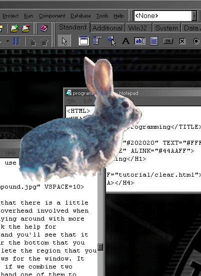
But I will, "quick - like a bunny" show you how it looks running.
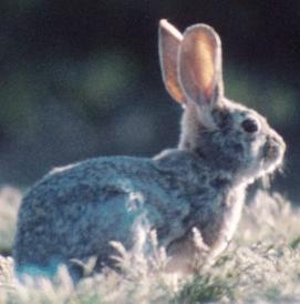
To give you an idea of where various aspects are coming from, here are the bitmap containing the color information...
And the bitmap containing the transparency information...
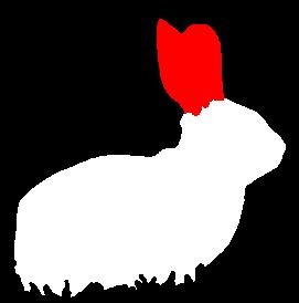
In the mask bitmap, any pixel that is white or red is interpreted in OnCreate as opaque and is added to the region for the window's shape. Any black pixels are skipped. At runtime, white pixels are considered normal client area and red areas are treated as non-client caption areas. Now, this "treating" and "interpreting" is not automatic. Those are the parts you actually have to write code for.
Why the colors I chose? No particular reason. An alpha channel is frequently treated as Opaque=Full Value=White, so it seemed reasonable for me to treat the white in a familiar way. The red has no such history. If you think that you or your users would rather have green be transparent and yellow opaque and orange be treated as HTCAPTION, then by all means, it is your code.
So far, the code is only set up and tested with 24bit .BMP files. This is because I fairly well understand 24bit DIBs and bunnies look best in full color. It shouldn't be hard to make it work with JPEGs.
Guess it's time to look at the code...
  WindowRgn := CreateRectRgn(0,0,0,0);
  for row := 0 to height-1 do
    begin
    RowRgn := CreateRectRgn(0,row,0,row);
    sl := maskMap.scanline[row];
    spanleft := 0;
    spanright := 0;

    repeat
      GetNextSpan(sl,spanleft,spanright,spancolor);
      case spancolor of
         clWhite,clRed:
           begin
           SpanRgn := CreateRectRgn(spanleft,row,spanright+1,row+1);
           CombineRgn(RowRgn, RowRgn, SpanRgn, RGN_OR);
           DeleteObject(SpanRgn);
           end;
         else
           {do nothing}
         end; {case}
      spanleft:=spanright+1;
    until (spanright >= width);

    CombineRgn(WindowRgn, WindowRgn, RowRgn, RGN_OR);
    {Delete all created regions except the final window region}
    DeleteObject(RowRgn);
    end; {row looping}
  SetWindowRgn(Handle,WindowRgn,true);
OK, I'm not going to pretend that that's ALL the code, but it is the most important part. If you have a look at it and are feeling totally lost, go back to the program that determines its transparency based on controls. It works the same way that this one does.
The basic three step process is the same - 1) create an empty region; 2) iterate though the determinor and add rectangles to the empty region; 3) SetWindowRgn with the newly built up region. Start Count Finish. Three steps.
In the control based app, the rectangles used are the rectangular limits of a given control. In the bitmap based app, the rectangles used are the rectangular limits of a group of pixels.
First, an ASIDE. At first, this program looked at each pixel and if needed created a rectangular region one pixel big. This region was then added into the main region. That DID make the code a little more simple. What you see above uses a call to GetNextSpan to retrieve a continuous horizontal group of pixels (n pixels wide by one pixel tall) of the same colour...
WindowRgn := CreateRectRgn(0,0,0,0)
This creates an empty rectangular region. As the program steps through the mask bitmap, it wil add new rectangular regions to WindowRgn.
  for row := 0 to height-1 do
    repeat
    until (spanright >= width);
This is the main control loop. Across and down to cover a two dimensional bitmap.
RowRgn := CreateRectRgn(0,row,0,row);
Program creates a fresh new blank region to accumulate region information for a single scan line. This just might be unnecessary.
sl := MaskMap.scanline[row];
scanline hands back a TBytePointer to a given row (scan line) of pixel data for a bitmap. Look for it in the help.
case
GetNextSpan returns the position of the left and right ends of a continuous row of colours in the current scanline (sl). It also returns the colour that makes up the span. At form creation, it only matters which parts are clear and which not. So white and red are treated the same. Any other colour is not considered a valid opaque area so it is not added to the region.
  clWhite,clRed:
    begin
    SpanRgn := CreateRectRgn(spanleft,row,spanright+1,row+1);
    CombineRgn(RowRgn, RowRgn, SpanRgn, RGN_OR);
    DeleteObject(SpanRgn);
    end;
Here are three lines that are almost exactly the same as in the control based app. Some of the variable names are changed to help readability in the context of bitmaps and the region created is known to be one pixel high because only one scan line at a time is tested. Otherwise, create a temporary region that is the size of a known opaque area; RGN_OR that region into the main region being created for this whole scan line; delete the temp region.
spanleft:=spanright+1;
GetNextSpan is about to be called again, and it knows where to start looking in the scanline by my telling it through spanleft.
Let's step back a few lines to right after GetNextSpan returns. It leaves the left and right "pointers" to pixels that are at the extreme ends of a group of similar colours. Like so...
  --------********------************----
          L      R
The region code then uses this data to in creating the window region. By advancing the left "pointer" to the pixel after the rightmost, I know that GetNextSpan will start looking for pixels at just the right place - a new run of colour...
  --------********------************----
                  L
The scanline is finished and it is time to move on to the next one. But first...
  CombineRgn(WindowRgn, WindowRgn, RowRgn, RGN_OR);
  DeleteObject(RowRgn);
The region built for this scanline needs to be added into the region being built for the whole window. Then, it is no longer needed. A new one will be made at the start of the next scan line.
SetWindowRgn(Handle,WindowRgn,true);
No surprises here, actually need to tell Windows to use the region that we just spent all that effort to create.
I don't know if I have gained anything by making separate row regions for each scanline. I should run time tests someday to see if just adding the span regions to the main window region is a speed up or slow down thing.
There is, of course, more code than above. There is the scanline parser which hands back nice little spans of colour. There is the function which interprets colours allowing for them to be not quite pure WHITE. If you care, download the project. There's less than 200 lines of source, and a fair bit of that is comments.
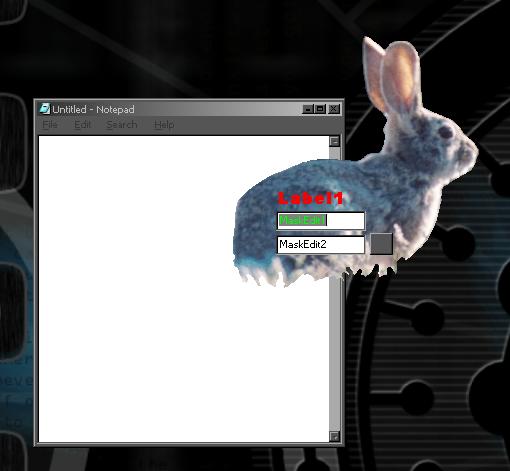
Here's the bunny with some controls placed on the form. Works perfectly fine...
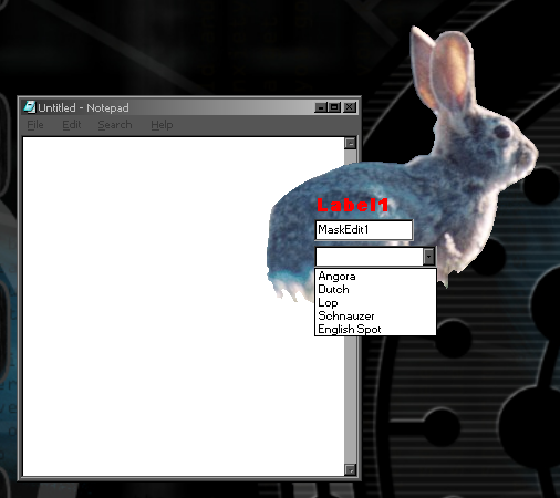
And just to show that Windows takes care of drop down list boxes all by itself...
A rectangular window region is probably one of the most efficient for Windows to deal with and on a slower machine or a slow graphics card (try the vanilla VGA driver) Windows can have a hard time repainting areas the app moves over. This doesn't seem to be a problem and can be fun to play with. Making little bunny trails...
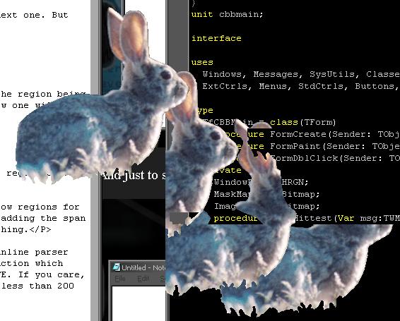
People ask how fast the ClearByBitmap program is. It can take a little time on the larger bitmaps for it to show, but it isn't that bad. One bitmap I did try that took a fair bit of time is both big at over 700x700 pixels and complex in that it has lots of small independant areas of pixels. While the app performed OK, Windows did seem to actually get confused by it, sometmies not properly refreshing areas that it moved over...
 Download Project